 The lack of modulation on the data sign also made the drive quite sensitive to the disk speed. The unit didn't shield the drive in any respect, putting the r/w head and associated analog amplifier and sign conditioning circuitry inches away from a excessive voltage CRT and also the switching energy provide. Any small noise voltage attributable to a distinction in floor potential which will couple into the circuit (primarily at energy line frequencies and its harmonics) is not going to have an effect on digital circuits and can usually be filtered out of rf circuits, due to the big frequency distinction. This technique is often simpler stated than achieved, especially when the frequencies involved could be within the range of hundreds of megahertz or extra. The important thing to the effectiveness of this method is reaching a low impedance (at the frequencies of interest) in the PCB-to-chassis connection. The 601-205 Calibration Key is designed to be used with 600-058, 600-061, 601-211 and 601-212 manual banding instruments. The 601-211 (M81306/1C) and 601-212 (M81306/1D) Tension Gauge is used to verify and calibrate the manual tool to values noted on calibration sticker. To that finish, this business advisory is meant as formal notification that the improper mixing of non-suitable band straps and tooling will void any guarantee offered by Glenair, and in our expertise, will absolutely result in device injury and sub-commonplace shield terminations.
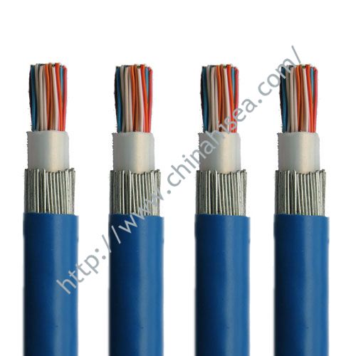
 The inside shield can then be terminated at only one finish, thus avoiding the bottom-loop coupling that may happen if grounded at each ends. Thus, the shield is often related at one finish, and disconnected at the opposite side. As was discussed in Section 2.5.2, a shield supplies no magnetic field protection at low frequency. However, at excessive frequency, the capacitor turns into a low impedance, which converts the circuit to 1 that's grounded at both ends. However, to be effective at RF, the parasitic inductance of the capacitors have to be as low as possible. Within the first case, the two shields could be in contact with each other; in the second case, the 2 shields should be isolated from one another (also known as a triaxial cable). This voltage will drive a typical-mode present out on the cable, and can cause the cable to radiate. Create a seperate I/O space and i/O floor aircraft on the circuit board, allowing the chassis-to-circuit floor connection to be made with minimum widespread-mode present stream.
Any impedance between the circuit ground and the chassis will produce a voltage drop, and can excite the cables with a common-mode voltage, which causes them to radiate. If one aspect just isn't appropriately designed, generally beyond our management, a standard-mode noise current flows and creates increased interference, as beforehand described. The potential distinction across the 2 conductors create a noise current movement throughout the complete cable's length, creating widespread-mode radiation. After the metallic enclosure is zapped by ESD, the circuit floor potential is held by the cable, enabling a secondary ESD strike could develop from the chassis to the circuit floor, finally leaving the system through an connected cable. A shielded twisted pair has traits similar to a triaxial cable and isn't as costly or awkward. Two causes to use a double- shielded cable are as follows: One is to increase the excessive-frequency shielding effectiveness; the opposite is when you've both high-frequency and low- frequency alerts in the identical cable. The ID blocks are created on the time the disk is formatted. Because of this when reading from or writing to the floppy, the serial port is disconnected and any transfers during that point are misplaced.
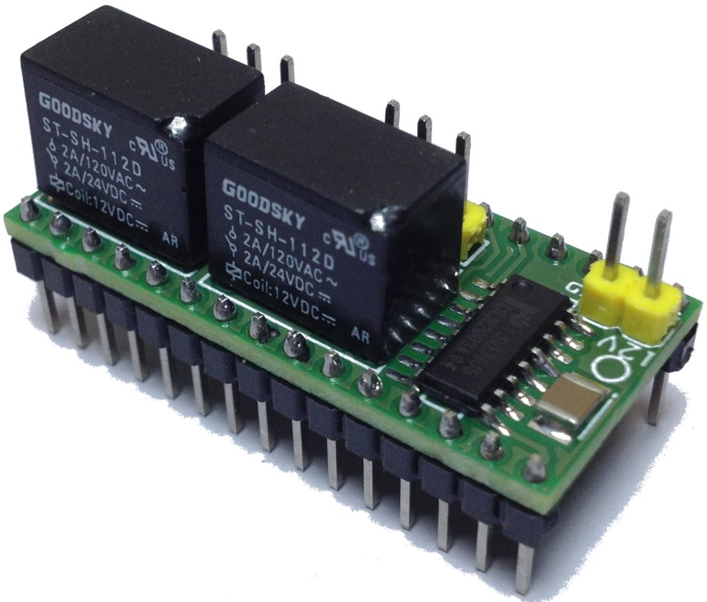
When terminating a twisted pair, the more the two wires are separated, the less the noise suppression. As well as, any shield present current is equally coupled (ideally), by mutual inductance, to each internal conductors and the two equal noise voltages cancel. In an previous-college design the connectors are screwed onto the chassis, so a shield-to-chassis connection is sort of all the time the prefered path for noise present. But in fashionable designs, connectors are mounted onto the circuit board, not the chassis. Precision bands and tools are exactingly dimensioned and calibrated for repeatable, reliable efficiency. Made in America, with business-main guaranteed quality and dependable efficiency. Slim bands are 50% lighter with 50% lower profile than our standard bands, while maintaining related efficiency. At a later point they switched to a four-part stepper design; although the interface is the same, the phase controls are decoded right into a 4 phase drive to the stepper motor. The electrical interface was rather simple, and anything not strictly essential was not supported. No modulation scheme is employed in recording to the disk (such as FM, MFM, or GCR), which is problematic.
When you loved this informative article and also you would want to acquire more details with regards to shield control cable generously go to the web-page.